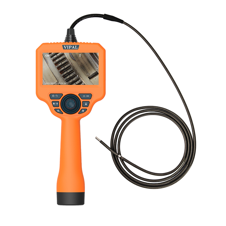

Industrial Borescope Inspection Checklist | Practical Guide
Category: Technical Support-
On: 2026-09-02
1. Introduction
High-quality industrial borescope inspection involves much more than using a high-resolution camera. A reliable RVI (Remote Visual Inspection) process requires systematic preparation, probe selection, equipment checks, standardized inspection procedures, image adjustment, multi-angle verification, data recording, and equipment maintenance.
Missing any of these steps can increase the risk of missed defects, poor image quality, incomplete inspection records, or equipment problems.
This industrial borescope inspection checklist is designed as a practical guide for inspection personnel. It covers the complete workflow from pre-inspection preparation and inspection procedures to defect documentation and post-inspection maintenance.
It can be used as a practical reference for standardized RVI and visual inspection operations, helping ensure that inspection results are consistent, accurate, and traceable.
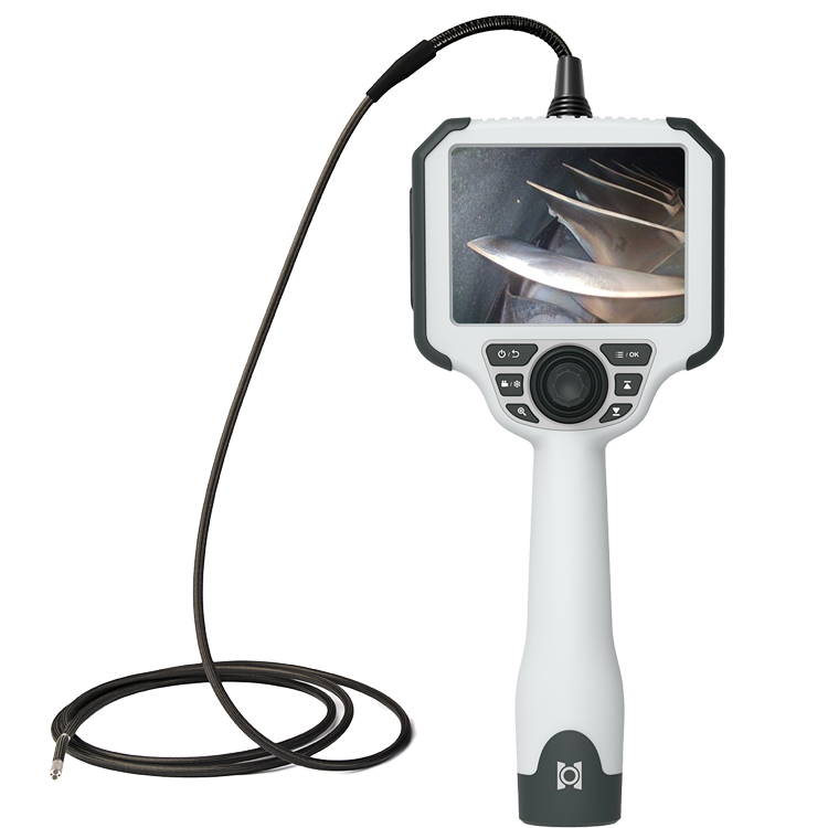
2. Pre-Inspection Preparation
2.1 Define the Inspection Target and Scope
Before starting the inspection, clearly identify the equipment, inspection areas, critical components, and acceptance criteria.
Typical inspection targets include:
Gear teeth
Internal engine components
Pipeline walls
Casting cavities
Bearings
Internal mechanical structures
Enclosed equipment cavities
Determine in advance which types of defects need to be identified, such as cracks, wear, carbon deposits, corrosion, foreign objects, burrs, or surface damage.
A clearly defined inspection scope helps prevent unnecessary probing and ensures that critical areas are not overlooked.
2.2 Confirm the Access Opening Size
Measure the minimum diameter or opening size of the inspection port, access hole, or internal passage.
This determines the maximum allowable probe diameter.
A probe that is too large may not enter the equipment, while an unnecessarily small probe may provide lower image quality, illumination, or mechanical durability depending on the application.
Always confirm the actual access dimensions before selecting the borescope.
2.3 Estimate Inspection Depth and Select Probe Length
Estimate the distance from the access opening to the furthest inspection target.
When the inspection path contains bends or complex internal structures, consider the actual probe travel path rather than relying only on the straight-line distance.
Select a suitable borescope probe length with enough working range to reach the target while maintaining good control of the insertion tube.
2.4 Evaluate the Inspection Environment
Check the operating conditions before bringing the borescope into the equipment.
Important factors may include:
Ambient temperature
Water or moisture
Oil and grease
Dust and debris
Humidity
Chemical exposure
Other application-specific conditions
Make sure the borescope and probe are rated for the actual inspection environment.
2.5 Perform a Pre-Inspection Equipment Check
Before inserting the probe, perform a complete equipment inspection. Never begin an inspection with damaged or contaminated equipment.
Check the following:
Probe condition: No visible damage, deformation, excessive bending, or contamination
Camera lens: Clean, clear, and free from scratches or deposits
Lighting system: Uniform illumination without flickering or dark areas
Articulation: Smooth directional control with no sticking or abnormal resistance
Display: Clear image with normal operation
Battery: Sufficient charge for the planned inspection
Storage: Adequate storage capacity for photographs and videos
Recording functions: Photograph and video recording operate normally
Camera tip: Clean the distal end when necessary to ensure image clarity
This simple pre-check can prevent many avoidable inspection failures.
3. Standardized Borescope Inspection Procedure
3.1 Insert the Probe Smoothly
Insert the probe slowly and smoothly.
Never force the insertion tube through a restricted passage or apply excessive bending force. Rough handling can damage the probe, camera tip, or internal surfaces of the inspected equipment.
This is particularly important when inspecting precision components such as engines, castings, gearboxes, and narrow pipelines.
3.2 Adjust Illumination Carefully
Adjust the light intensity according to the internal surface material and reflectivity.
If the illumination is too low, small defects may be hidden in dark areas. Excessive illumination can cause glare, reflections, or image washout that obscures surface details.
The objective is to obtain a balanced image with clear surface texture and visible defect characteristics.
3.3 Position the Viewing Angle
Use the probe's articulation or steering function together with controlled insertion, withdrawal, and rotation to position the camera at the appropriate viewing angle.
For critical inspection areas, take time to find the viewing angle that provides the clearest representation of the surface.
Proper camera positioning is especially important when inspecting cracks, pitting, scratches, corrosion, and other small surface defects.
3.4 Perform a Systematic Full-Coverage Inspection
Avoid random probing.
Follow a defined inspection path to minimize the risk of missed areas:
Access Point → Near Section → Intermediate Section → Critical Target Components → Surrounding Surfaces → Return Inspection
A systematic inspection sequence provides better coverage and makes the inspection process easier to repeat and document.
3.5 Verify Critical Areas from Multiple Angles
A defect may not be visible from a single viewing direction.
For critical components and suspected defects, change the camera angle and inspect the area from multiple directions.
Multi-angle verification can help confirm the actual shape, location, and appearance of cracks, pitting, impact damage, corrosion, and other abnormalities.
4. Defect Identification and Inspection Data Recording
4.1 Standard Image and Video Recording
Proper documentation is an essential part of RVI.
High-Resolution Photographs
Capture clear close-up images of:
Defect locations
Representative operating conditions
Reference or acceptable surfaces
Critical components
High-quality images provide direct visual evidence for later analysis and reporting.
Inspection Videos
For large inspection areas, complex cavities, or areas where spatial context is important, record inspection videos.
Video can preserve the relationship between the defect and surrounding structures and provide additional evidence for later review.
Location Identification
Clearly identify where each image or video was captured.
For inspections involving multiple areas or components, use consistent location references to prevent inspection data from being mixed up.
4.2 Complete Defect Documentation
Whenever an abnormal condition is identified, record the relevant information completely.
Recommended records include:
Defect location
Defect type, such as wear, crack, carbon deposit, corrosion, or foreign object
Approximate defect dimensions when measurable
Corresponding photographs and videos
Inspection date
Equipment or component identification
Inspector information
Complete records improve traceability and support maintenance, quality inspection, and acceptance procedures.
4.3 Defect Measurement
If the borescope is equipped with a measurement function, follow the manufacturer's recommended measurement procedure.
Depending on the system and application, measurements may include:
Crack length
Defect width
Pitting size
Wear dimensions
Other measurable surface abnormalities
Measurement results should be interpreted according to applicable industry standards, engineering requirements, and equipment-specific acceptance criteria.
5. Post-Inspection Procedures and Equipment Maintenance
5.1 Remove the Probe Carefully
Withdraw the probe slowly and carefully.
Avoid sharp edges, corners, and other structures that could damage the insertion tube or camera tip.
Do not pull the probe forcefully when resistance is encountered.
5.2 Clean and Maintain the Equipment
Follow the manufacturer's maintenance instructions to clean the insertion tube and camera tip.
Remove oil, dust, moisture, and other contaminants after the inspection.
Proper cleaning helps maintain image quality and extends the service life of the inspection equipment.
5.3 Archive Inspection Data
Organize and store all photographs, videos, measurement results, and inspection records.
Where required, generate a standardized inspection report and organize the data according to equipment, component, inspection date, or project.
A well-organized archive allows inspection results to be:
Retrieved later
Compared with previous inspections
Reviewed by engineers
Used for maintenance planning
Verified during quality or acceptance procedures
5.4 Perform a Final Equipment Check
Before storing the borescope, inspect the probe and equipment again.
Check for:
New damage
Deformation
Excessive wear
Contamination
Damage to the camera tip
Abnormal articulation
Address any problems before the next inspection to ensure equipment readiness.
6. Industrial Borescope Inspection Checklist
Use the following checklist as a quick reference during field inspections.
Before Inspection
□ Define the inspection target and defect criteria
□ Measure the access opening and determine the appropriate probe diameter
□ Estimate inspection depth and select the appropriate probe length
□ Check temperature, moisture, dust, oil, and other environmental conditions
□ Inspect probe condition and camera lens cleanliness
□ Check battery level and available storage
□ Test illumination and image quality
□ Check probe articulation and steering operation
During Inspection
□ Insert the probe smoothly without excessive force
□ Adjust illumination for the inspected surface
□ Position the camera at the appropriate viewing angle
□ Follow a systematic inspection path
□ Inspect the complete target area without unnecessary gaps
□ Verify critical areas from multiple viewing angles
□ Capture high-resolution images of important findings
□ Record videos where additional inspection context is required
□ Measure defects when the equipment supports measurement
□ Record defect location, type, size, and related inspection information
After Inspection
□ Withdraw the probe carefully
□ Clean the probe and camera tip
□ Organize and archive photographs, videos, and measurement data
□ Complete the inspection report
□ Check the probe for damage or deformation
□ Store the equipment according to the manufacturer's instructions
7. Conclusion
The accuracy and consistency of an industrial borescope RVI inspection depend not only on the hardware but also on the quality of the complete inspection procedure.
Proper preparation, appropriate probe selection, controlled probe handling, optimized illumination, systematic inspection coverage, multi-angle defect verification, complete digital documentation, and proper equipment maintenance all contribute to reliable inspection results.
Following a standardized borescope inspection checklist can help reduce the risk of missed defects, improve inspection consistency, and make inspection results easier to review, compare, and trace.
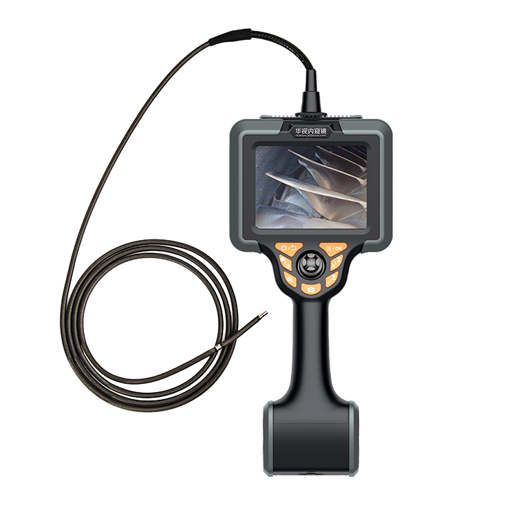
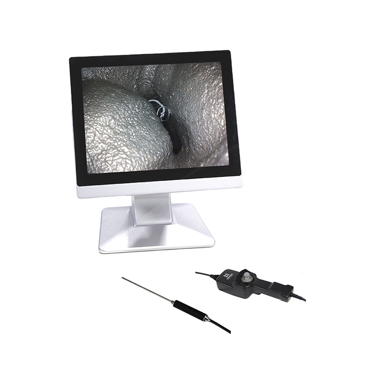
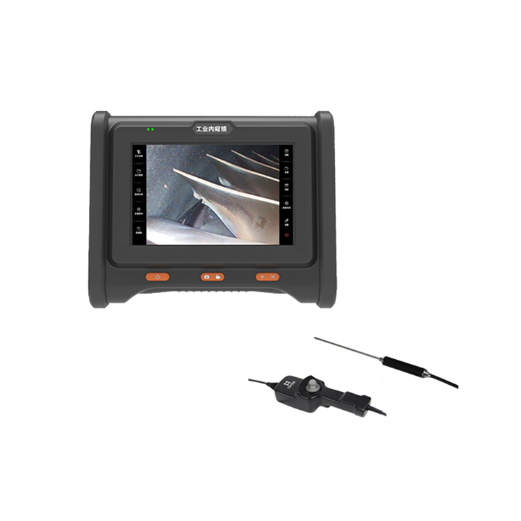
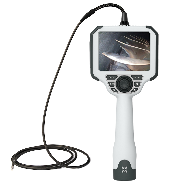
For modern industrial visual inspection, a high-quality industrial videoscope combined with a standardized inspection workflow provides an efficient approach to non-destructive examination of engines, gearboxes, pipelines, castings, turbines, machinery, and other hard-to-reach internal structures.