
Turbine Blade Borescope Inspection: What Should Inspectors Check?
Category: News-
On: 2026-09-08
Turbine blades are critical components in aircraft engines and gas turbine equipment. During operation, they are exposed to high temperatures, high rotational speeds, vibration, gas flow, particulate erosion, corrosion, and foreign object impacts.
These demanding conditions can cause a variety of surface and near-surface damage. If damage is not identified and evaluated appropriately, it may affect equipment performance, maintenance decisions, and operational safety.
However, turbine blades are located deep inside the engine or turbine casing, making direct visual access difficult. Complete disassembly can require significant maintenance time and cost.
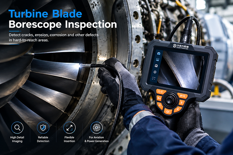
Turbine blade borescope inspection, also known as a form of Remote Visual Inspection (RVI), allows inspectors to access internal areas through suitable inspection ports using a flexible industrial videoscope. When permitted by the applicable maintenance procedure and equipment condition, this approach can reduce the need for extensive disassembly and provide rapid visual access to turbine blades and surrounding components.
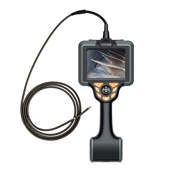
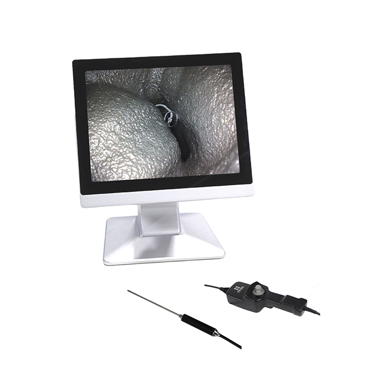
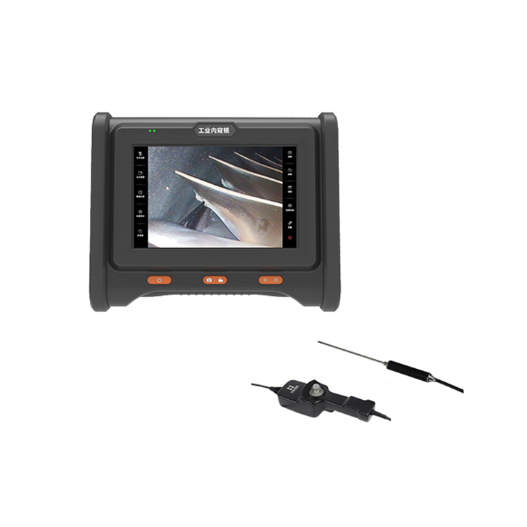
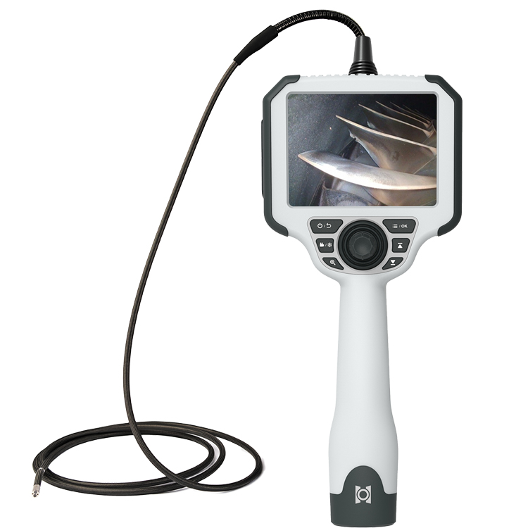
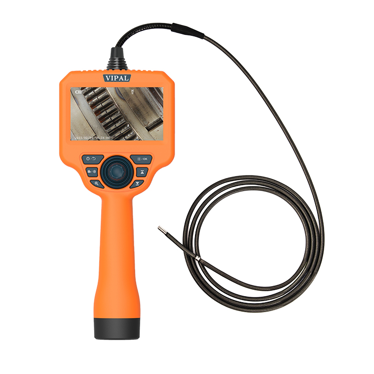
A suitable turbine inspection borescope combines a flexible probe, steerable articulation, high-quality imaging, and integrated illumination to help inspectors navigate confined spaces, examine blade surfaces, and document visible findings.
The choice of borescope directly affects inspection accessibility, image quality, defect visibility, and overall inspection efficiency.
What Is Turbine Blade Borescope Inspection?
Turbine blade borescope inspection is a Remote Visual Inspection (RVI) technique used to visually examine turbine blades and other internal components without necessarily performing extensive equipment disassembly.
A typical industrial videoscope system includes:
Flexible insertion probe
Miniature camera module
Integrated LED illumination
Multi-way articulation mechanism
Portable display unit
Image and video recording
Internal or removable storage
Optional measurement functions
The probe is inserted through an appropriate inspection port and guided toward the target area. The inspector uses the articulation control to position the camera and observe accessible blade surfaces.
Images and videos can then be recorded as inspection evidence.
The exact inspection points, access conditions, inspection procedure, and acceptance criteria must always follow the OEM maintenance documentation, approved inspection procedure, and applicable industry requirements.
Why Is Turbine Blade Borescope Inspection Important?
1. Access Internal Areas That Are Difficult to Observe Directly
Turbine blades are enclosed within the engine or turbine casing and cannot normally be inspected directly with the naked eye.
A flexible borescope can pass through suitable inspection ports and reach difficult-to-access areas, allowing inspectors to examine visible portions of:
Blade airfoils
Leading edges
Trailing edges
Pressure surfaces
Suction surfaces
Blade roots
Platforms
Other accessible internal components
The actual areas that can be inspected depend on the equipment design, access ports, probe dimensions, and inspection procedure.
2. Reduce the Need for Extensive Disassembly
When inspection conditions and maintenance procedures permit, borescope inspection can provide internal visual access without major disassembly.
This can help reduce:
Inspection preparation time
Disassembly and reassembly work
Maintenance labor
Equipment downtime
However, a borescope should not automatically be described as a "no-disassembly" solution. Some inspections still require partial or complete disassembly according to the OEM procedure.
3. Identify Damage Before It Becomes More Serious
High-quality visual inspection can help identify visible damage at an early stage.
Detecting and documenting changes such as cracks, erosion, foreign object damage, or coating deterioration can support maintenance decisions before damage progresses.
The significance of each finding must be evaluated against the applicable maintenance limits and inspection criteria.
4. Create Traceable Inspection Records
Photos and videos provide valuable documentation for:
Maintenance reports
Defect records
Technical evaluation
Maintenance planning
Condition comparison
Historical inspection records
When inspection data is consistently documented, previous and current findings can be compared to help track changes over time.
5. Improve Inspection Accessibility and Efficiency
A steerable probe allows the inspector to change the camera direction inside confined spaces.
A 4-way articulating borescope can provide control in multiple directions, typically up/down/left/right, depending on the system design.
This can be particularly useful when the target blade is not directly aligned with the insertion path.
What Should Inspectors Check During Turbine Blade Borescope Inspection?
Important: Borescope inspection is primarily a visual inspection method. Findings should be assessed according to the applicable OEM documentation, maintenance manual, inspection procedure, and acceptance criteria. Suspected defects may require additional NDT methods for confirmation.
1. Cracks
Cracks are among the most important findings to look for during turbine blade inspection.
Inspectors may pay particular attention to:
Leading edges
Trailing edges
Airfoil surfaces
Blade roots
Platforms
Geometric transitions
Other areas identified as high-risk by the applicable inspection procedure
A borescope can reveal visible crack indications, but visual inspection alone generally cannot determine the complete crack depth or subsurface extent.
When a crack is suspected, additional inspection methods such as penetrant testing or ultrasonic testing may be required, depending on the component and applicable procedure.
2. Erosion
High-velocity gas flow containing particles can gradually remove material from turbine blade surfaces.
Typical visual indications include:
Leading-edge erosion
Local material loss
Surface wear
Changes in blade profile
Localized damage
Significant erosion can affect the blade's aerodynamic profile and may require engineering evaluation against applicable limits.
3. Corrosion
Turbine components can be exposed to contaminants, moisture, combustion by-products, or other corrosive conditions.
Inspectors may look for:
Surface discoloration
Pitting
Oxidation
Localized surface deterioration
Corrosion associated with deposits
Clear images can document the location and appearance of visible corrosion for subsequent assessment.
4. Thermal Damage
Turbine blades operate in high-temperature environments and may experience thermal fatigue, overheating, or thermal degradation.
Inspection points can include:
Burn marks
Abnormal discoloration
Heat-related cracking
Surface deterioration
Thermal barrier coating damage
Localized overheating indications
The appearance and significance of thermal damage should be assessed against the relevant maintenance criteria.
5. Foreign Object Damage (FOD)
Foreign Object Damage, or FOD, occurs when foreign particles or debris enter the flow path and impact turbine components.
Typical visible indications include:
Leading-edge dents
Nicks
Notches
Scratches
Local deformation
Material loss
Impact marks
Inspectors should document both the location and appearance of the damage.
For turbine blades, leading-edge damage is particularly important because it can affect the component's aerodynamic profile and structural condition.
6. Coating Damage
Many turbine blades use protective coatings designed to withstand demanding thermal and environmental conditions.
Depending on the component and coating system, inspectors may look for:
Coating delamination
Peeling
Cracking
Local coating loss
Surface abnormalities
Areas of exposed substrate
Coating condition can be an important part of turbine component assessment, particularly in high-temperature applications.
7. Blade Deformation
Thermal loading, mechanical forces, vibration, or impact can potentially cause changes in blade geometry.
Inspectors may look for:
Bending
Twisting
Warping
Abnormal blade shape
Differences between adjacent blades
If quantitative deformation data is required, a measurement videoscope may be considered.
However, visual measurement results should be interpreted according to the measurement system's capabilities and the applicable inspection procedure.
8. Deposits and Contamination
Combustion products, salts, particles, and other contaminants can accumulate on turbine blade surfaces.
Inspectors may look for:
Carbon deposits
Surface buildup
Uneven deposits
Scaling
Localized contamination
Heavy deposits may affect aerodynamic performance or heat transfer characteristics. Their significance should be evaluated according to the applicable maintenance criteria.
Standard Turbine Blade Borescope Inspection Procedure
A structured inspection procedure helps improve consistency and reduce the risk of missing important areas.
Step 1: Define the Inspection Task and Acceptance Criteria
Before starting, confirm:
Equipment type
Engine or turbine section
Inspection port
Target blade stage
Target components
Inspection coverage
Applicable maintenance documentation
Acceptance criteria
The inspector should understand the approved inspection procedure before inserting the borescope.
Step 2: Select the Appropriate Videoscope
Key selection parameters include:
Probe diameter
Usable probe length
Articulation range
Camera resolution
Illumination
Viewing direction
Field of view
Measurement capability
The probe must be physically compatible with the inspection port and internal geometry.
Step 3: Perform a Pre-Inspection Equipment Check
Before inserting the probe, verify:
Camera image
Illumination
Articulation
Probe sheath condition
Recording function
Storage capacity
Battery level
If measurement functions will be used, perform the required system checks or calibration procedures before inspection.
Step 4: Insert the Probe Through the Inspection Port
Insert the probe carefully through the approved access point.
Avoid excessive pushing force or aggressive manipulation, which could damage the probe or contact internal components.
Probe movement should follow the applicable inspection procedure and equipment-specific precautions.
Step 5: Navigate to the Target Blade
Use the articulation control to adjust the distal tip direction.
A 4-way articulating probe can provide up/down/left/right directional control, making it useful when the inspection path contains curves or when the target is offset from the insertion axis.
Step 6: Inspect the Blade From Multiple Viewing Directions
Where accessible and required by the procedure, inspect:
Leading edge
Trailing edge
Pressure surface
Suction surface
Platform
Blade root
Other specified areas
Viewing the same area from different positions can reveal surface features that may not be obvious from a single viewing direction.
Step 7: Adjust Illumination
Metallic internal surfaces can create strong reflections.
Adjust illumination to achieve a useful balance between:
Image brightness
Surface detail
Reflection control
Shadow reduction
Excessive illumination can create glare that hides small surface indications.
Image quality also depends on the camera, optics, probe diameter, illumination system, and working distance.
Step 8: Capture Images and Video Evidence
When a potential defect is identified, record appropriate documentation.
Useful records may include:
Overall view
Defect close-up
Location information
Blade or stage identification
Inspection date
Relevant equipment information
Video can also provide useful context by showing the defect and surrounding area during probe movement.
Step 9: Perform Measurement When Required
If the videoscope includes a suitable measurement function, visible defects may be measured where the inspection system and procedure permit.
Depending on the system, measurements may include:
Crack length
Damage width
Dent dimensions
Damaged area
Other measurable geometric features
Measurement accuracy depends on the measurement technology, calibration, optics, working distance, target surface, image quality, and system algorithms.
For critical findings, measurement results should be evaluated according to the applicable procedure and confirmed with additional inspection methods when required.
Why Is 4-Way Articulation Important for Turbine Inspection?
The internal geometry of turbine systems can be complex, while blades are arranged around the flow path in multiple orientations.
A 4-way articulating borescope allows the distal tip to be controlled in multiple directions, typically:
Up + Down + Left + Right
This gives the inspector greater directional control without repeatedly repositioning the entire probe.
It can be particularly useful for:
Angled blade surfaces
Curved inspection paths
Offset inspection targets
Complex internal geometries
However, 4-way articulation does not make a borescope suitable for every turbine inspection.
Probe diameter, insertion length, minimum bending radius, camera performance, illumination, and access geometry remain equally important.
Forward View, Side View, or Dual View: Which Is Better?
Different viewing configurations are suitable for different inspection geometries.
Forward-View Borescope
The camera looks toward the front of the probe.
Viewing Direction: 0°
Forward view is useful when the target is positioned directly ahead of the probe.
Side-View Borescope
The camera observes the area to the side of the probe.
Viewing Direction: 90°
Side view can be useful for examining surfaces that are difficult to observe with a forward-facing camera.
Dual-View Borescope
A dual-view system provides both forward and side viewing, depending on the system design.
This can reduce the need to repeatedly reposition or change inspection equipment when both viewing directions are required.
For turbine inspection, the best configuration depends on the inspection port, blade geometry, target location, and approved inspection procedure.
How Does Probe Diameter Affect Turbine Blade Inspection?
Probe diameter is primarily determined by the minimum access opening.
Small-Diameter Probe
Advantages:
Can pass through smaller inspection ports
Better suited to restricted spaces
Useful for narrow internal passages
Considerations:
Smaller physical space for the camera and illumination system
Potential limitations in image performance depending on design
More delicate probe construction in some configurations
Larger-Diameter Probe
Advantages:
More room for imaging and illumination components
Potentially stronger mechanical construction
Can provide higher imaging performance depending on system design
Considerations:
Requires a sufficiently large access opening
May have more limitations in very restricted passages
The practical principle is:
Choose the largest probe that safely fits the required access opening and inspection path while providing the imaging performance you need.
How Long Should a Turbine Inspection Probe Be?
The usable probe length must be sufficient to reach the farthest required inspection area while allowing the inspector to navigate the internal path.
A probe that is too short may not reach the target.
A probe that is unnecessarily long may be more difficult to handle and store.
Consider:
Distance from inspection port to target
Internal geometry
Curved inspection paths
Probe flexibility
Articulation capability
Operator handling
For specialized turbine or engine applications, custom probe lengths may be appropriate.
Is Higher Camera Resolution Always Better?
Higher resolution can provide more image detail, but camera resolution alone does not determine overall inspection quality.
Other important factors include:
Image sensor
Optical system
Illumination
Focus
Field of view
Working distance
Image processing
For turbine blade inspection, a balanced imaging system is generally more valuable than simply selecting the camera with the highest nominal pixel count.
When Do You Need a Measurement Borescope?
A standard borescope primarily provides visual information about a defect.
If an inspection procedure requires quantitative information about a visible indication, a measurement borescope may be appropriate.
Depending on the system, measurement functions can support evaluation of:
Crack length
Dent size
Material loss
Damage width
Other visible geometric features
However, measurement results should not automatically be treated as a substitute for a qualified engineering assessment or another required NDT method.
When the inspection procedure requires confirmation of crack depth, subsurface damage, or another parameter that cannot be reliably established visually, additional NDT may be necessary.
Borescope Inspection vs. Other NDT Methods
A borescope is primarily a visual inspection / Remote Visual Inspection (RVI) method.
Its strength is observing and documenting accessible internal surfaces.
It does not replace every other NDT technique.
Depending on the component and inspection requirement, additional methods may include:
Ultrasonic Testing (UT)
Radiographic Testing (RT)
Magnetic Particle Testing (MT)
Penetrant Testing (PT)
Dimensional inspection
Other approved inspection techniques
Each method detects different types of indications.
A suitable inspection program combines methods according to the component, defect mechanism, applicable standard, and maintenance procedure.
10 Questions to Ask Before Buying a Turbine Inspection Videoscope
Before purchasing a turbine blade borescope, confirm the following:
What is the minimum inspection port diameter?
This determines the maximum probe diameter.How far is the target blade from the inspection port?
This determines the required probe length.Is the internal inspection path straight or curved?
This determines the articulation and flexibility requirements.Which blade surfaces need to be inspected?
This helps determine forward-view, side-view, or dual-view requirements.What is the smallest defect that needs to be identified?
This affects camera, optics, illumination, and probe selection.Is defect measurement required?
How should images and videos be stored and exported?
What are the environmental conditions?
Consider temperature, dust, humidity, and other site conditions.How frequently will the videoscope be used?
Frequent inspection may justify stronger emphasis on durability, ergonomics, and service support.Are custom probe specifications required?
Check whether the manufacturer can provide custom diameter, length, viewing direction, or other configurations.
WorldNDT Turbine Inspection Borescope Solutions
WorldNDT focuses on remote visual inspection solutions for industrial applications.
Depending on the inspection requirements, WorldNDT industrial videoscopes can be configured with:
Small-diameter flexible probes
4-way articulation
Forward-view, side-view, or dual-view configurations
High-resolution imaging
Integrated illumination
Photo and video recording
Measurement functions
Portable display units
Customized probe specifications
These configurations can support visual inspection of gas turbines, aircraft engines, gearboxes, and other enclosed industrial components.
For aerospace applications, equipment selection and inspection procedures should always be aligned with the requirements of the applicable aircraft, engine, OEM maintenance documentation, and approved inspection procedures.
Frequently Asked Questions
What is a turbine blade borescope?
A turbine blade borescope is an industrial videoscope used for Remote Visual Inspection of turbine blades and other internal components through suitable inspection ports.
What defects can a turbine borescope detect?
A borescope can help identify visible indications such as cracks, erosion, corrosion, FOD, thermal damage, coating damage, deformation, and deposits.
However, the visibility and significance of each defect depend on the inspection conditions and applicable acceptance criteria.
What is the best borescope for turbine inspection?
There is no single best model for every turbine.
Selection depends on the inspection port diameter, required probe length, internal geometry, articulation, viewing direction, image quality, illumination, measurement requirements, and applicable inspection procedure.
Is 4-way articulation important for turbine blade inspection?
It can be very useful when the inspection path is curved or the target is offset from the probe axis.
A 4-way articulating probe provides directional control in multiple directions, typically up, down, left, and right.
What probe diameter should be used for turbine inspection?
The probe must fit through the required inspection port and navigate the internal path.
When access allows, a larger probe may provide advantages in imaging and illumination, depending on the system design. The final choice should balance accessibility and imaging performance.
Can a borescope measure turbine blade damage?
A videoscope equipped with an appropriate measurement system can support measurement of visible surface damage.
However, measurement capability and accuracy depend on the specific technology and inspection conditions. Critical findings should be evaluated according to the applicable procedure.
Can borescope inspection replace other turbine NDT methods?
No.
Borescope inspection is primarily a visual inspection method. When the maintenance procedure requires UT, PT, MT, RT, or another NDT technique, those inspections must still be performed.
Conclusion
Turbine blade borescope inspection is an important Remote Visual Inspection technique for examining internal turbine components while potentially reducing the need for extensive disassembly when permitted by the applicable maintenance procedure.
During inspection, inspectors commonly look for:
Cracks
Erosion
Corrosion
Thermal damage
Foreign Object Damage (FOD)
Coating damage
Blade deformation
Deposits
The key equipment selection factors include probe diameter, usable length, articulation, imaging quality, illumination, viewing direction, recording, measurement capability, durability, and service support.
For complex turbine inspection paths, a flexible 4-way articulating videoscope can provide valuable directional control. Forward-view, side-view, and dual-view configurations can further improve access to different blade surfaces.
However, no single specification determines inspection performance. The most suitable turbine inspection borescope is the one that matches the actual inspection port, internal geometry, target location, required defect visibility, and approved inspection procedure.